Thursday 24 July 2014

DCC and DC Controllers fitted and twin oval of track laid

I have fitted the NCE ProCab DCC controller interface module into the baseboard edge, along with a socket to plug in an old H&M Analogue (DC) controller and a toggle switch to change the track feed from one controller to the other.
In this way I can run the layout as either DCC or DC with a simple toggle switch, here is a photo of the installation;

On the left on top of the baseboard is the DC controller plugged into the left hand socket. Next to that is the toggle switch, left for DC and right for DCC. Then comes the NCE DCC controller interface module set into the baseboard edge and finally on the right is the NCE DCC hand held controller itself (sitting in a holder fixed to the baseboard), the cable from the bottom of this controller is plugged into the interface module just to the left of the red led on the module.

I have now laid the twin track oval that allows continuous running of at least two trains at the same time, here is an overall photo;


And here are some staged photos of the layout and some of the stock I have so far aquired;


The three locos below were given to me by a friend. They were made by his Dad who was a keen GWR loco modeller, but who sadly recently died, The models are excellent metal kits and well worth a place on any layout.
The above model is finished in "Photographic Grey" livery. In the days before colour photos the railway companies would finish examples of new types of locos in this livery so that they would photograph well, they never usually entered service in this livery, after being photographed they would be re-painted in normal company livery. The accompanying black and white photos would be used for publicity or record purposes.


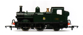
In the top photo above is a Hornby GWR 14xx Tank loco pulling a Hornby GWR Autocoach, this was a very common sight on GWR branchlines.
I purchased the loco secondhand from ebay as a British Rail veriant with the old BR Lion and Wheel logo but my layout is set in the Grouping days, before British Rail was formed, so I changed the loco from BR livery to GWR.


Here is a photo of the loco as delivered;

 
And as modified to GWR Livery


Finally, here is a link to a short (1 minute) video of this loco and autocoach making a circuit of the layout.


Thursday 12 June 2014

Laying the first pieces of track and a video of a loco running for the first time


So after many months of preparatory work I am finally at the stage of track laying.

I am using Peco Code 75 track with live frog turnouts and slips.
I have decided to lay some 3mm (1/8 inch) cork sheet and then pin the track onto that. Once all the track is laid I will then ballast with OO Gauge loose ballast fixed in place with a 50/50 mix of PVA adhesive and water, with a drop of washing up liquid.
For turnouts and slips I have cut the cork to the profile of the track.
For plain track I have cut the cork into 23mm (7/8 inch) strips which is half the width of the track bed. I then lay two strips either side of the track centre line, secured with neat PVA .
For the tighter curved track I mark the cork strip down the middle, then make cuts every 25mm (1 inch) along the cork strip from the edge into the mark. This makes the cork strip easy to curve round the track centre line.
Having glued the cork down (held in place with push pins while the glue dries) I then lay the track along the centre of the two cork strips and secure it with Peco track pins.

Here are some photos of track laying in progress;


Where two baseboards join together the track rail needs to be cut so the baseboards can be separated, but it is important that the ends of the track rail stay in registration both vertically and horizontally.
To facilitate this I have fixed a strip of copper clad paxolin strip the same width and thickness of a Peco sleeper to the edge of the baseboard with glue and track pins.
The track rail is then soldered to the copper clad strip either side of the join, and the track rail then cut through exactly in line with the baseboard edge.
Here is a photo of a baseboard join:
This join will be painted and then disguised with the loose ballast that will be laid on the track.
No matter how many times you split the baseboards and then put them back together again the track rails should always meet up in line with each other.


To operate the turnouts and slips I am using Peco passing contact lever switches mounted in a Peco switch console, like this:
These switch consoles will be mounted around the layout on the edge of the baseboards that contain the associated turnouts or slips. They provide a very neat way of controlling the turnouts and slips without having to have connecting wires all over the place, or a separate operating panel mounted (somewhere) and connected to the baseboards with multi plugs.
Peco provide different colour switches to go into the console and mine will be colour coded as follows:
Main Line (black)
Cross Country Terminus (yellow),
Branch Terminus (white)
Fiddle Yard (red).

Finally I have made a short (3.5 min) video of a loco and some wagons making a test run on the first section of track, follow the link below to view the video on Dropbox (make sure you have sound turned on for the full effect).

https://www.dropbox.com/s/hmuvhgtj0lop8ff/Railway.mp4


Thursday 29 May 2014

DCC Controller, DC Transformer and Baseboard wiring

As well as using DCC control for the Locos I will need 16v ac for the Capacitor Discharge Unit (CDU) to fire the turnouts motors over and 12v dc for the Signals, Building and Street Lights and to drive a small hand held analogue DC controller for testing Locos that have not yet been chipped (converted to DCC operation).

To supply these additional voltages I am using an old H&M Powerpack, here is a front and back view;


Front View

This Powerpack supplies 16v ac from the left hand side banana connectors (yellow),
12v dc from the rear screw terminals.
12v dc from the right hand side banana connectors (from a separate winding of the transfomer so electrically separate from the rear 12v dc supply)


Rear View

I have made up a special cable to connect all three supplies to the layout via a 6 pin XLR female plug fixed to the black cable left, and a male XLR socket (fixed into the baseboard). This type of plug is used in the music industry for connecting microphones, speakers, amps etc and is extreemly robust.
 The black cable left has 3 pairs of wires as follows;
16v ac - two yellow banana plugs (right in photo) supply to the CDU
12v dc - red and black banana plugs (left in photo) supply for Building and Street lights, also supply for hand held DC Controller
12v dc - red and black spade terminals (centre left) supply for Signal control.


Here is a photo of the male XLR socket fitted to the underneath of the right hand baseboard;

The male XLR socket is to the right in the photo.
Also in the photo, to the left of the XLR socket is a male 2.5 X 5.5mm DC Chassis Socket.
I want to have all the power connections in one place on the baseboard, so this socket will take the plug from the NCE DCC Controller 6v dc PSU. Connected to this socket is some twin speaker cable which runs through this and the next baseboard to where the DCC controller pcb will be mounted. On the end of the speaker cable is a male 2.5 X 5.5mm plug which plugs into the DCC controller pcb.
The result of this is that I can have the DCC mains psu and H&M Powerpack co-located in a double mains socket, and connected to the baseboard with only two cables (one each).

The two 12v dc supplies, CDU output bus, DCC bus and 6v dc DCC controller supply run along under the baseboard using the coloured wires shown in these photos;

,

The CDU is mounted under the baseboard to the left of the main power connector socketss, here is a photo;

It has a 16v ac input and provides a 20v dc output to crisp;y fire the turnout motor.


Finally, I have revised the wiring scheme for the layout as follows;

DCC Feed (balanced pair)
DCC Bus (32/0.2)
Black (outer rail)
Red (inner rail)
Drop Wires (16/0.2)
Black (outer rail)
Red (inner rail)

Turnout (t/o) motors Capacitor Discharge Unit (CDU) 
CDU Feed from transformer to CDU (32/0.2)
Black - 16v AC pair
CDU output Bus (32/0.2)
Green (t/o motor common 20v dc -ve)
Yellow (t/o operating switch common 20v dc +ve)
Drop Wires (16/0.2)
Blue - t/o operating switch to t/o motor left coil
Brown - t/o operating switch to t/o motor right coil

Standard DC to operate signals
12v dc Bus (32/0.2)
White (signal motor common 12v dc -ve)
Orange (Signal operating switch common 12v dc +ve)
Drop Wires (16/0.2)
Grey - signal operating switch to signal motor "on"
Violet - signal operating switch to signal motor "off"

Controlled DC feed for non chipped locos (using small H&M controller)
Feed from transformer to controller and output from controller to track via switch (32/0.2)
Green (+ve)
White (-ve)

Lighting feed (use same transformer output as Controlled DC feed above)
12v dc Lighting bus (32/0.2)
Blue (+ve)
Yellow (-ve)
Drop Wires (16/0.2)
Blue (+ve)
Yellow (-ve)

Turnout and Slip Frog to turnout motor change over switch
White (16/0.2)

Now I have the main supply and bus wiring done on this baseboard I can finally get down to laying some track, so this is what I will be doing next.


Wednesday 7 May 2014

Layout wiring, including preparing Turnouts (Points) for installation

Since my last post I have been working out the track plan on the finished baseboards, this has taken a lot of thought and experimentation, but happy with it now, more on this in a later post.

So started to think about the wiring.
I am going to use a colour coded bus system to take the following feeds arpound the baseboards:

DCC Main Bus (balanced pair)
Black (outer rail) Red (inner rail)

Capacitor Discharge output to operate turnout (t/o) motors (20v dc +ve/-ve )
Green (t/o motor common) Yellow (t/o operating switch common)

Standard DC to operate signals (12v dc +ve/-ve)
White (signal motor common) Orange (signal operating switch common)

I will then take "drop" wires from the rails (Black/Red), t/o motors (Green), signal motors (White) and switches (Yellow/Orange) and connect them to the relevant "bus" wires using "Quick Splice" connectors, which alleviates the need to cut and solder any wires under the baseboard.

In addition the following coloured wires are also required;
Blue - t/o operating switch to t/o motor left coil
Brown - t/o operating switch to t/o motor right coil
Grey - signal operating switch to signal motor "on"
Violet - signal operating switch to signal motor "off"
These wires will go direct from the relevant switch to the t/o or signal motor.


The main bus wires are 32/0.2 stranded copper and the drop wires are 16/0.2 stranded copper.

Quick plug (get it?), I purchased all the wire and connectors on Ebay from "cm3models" who have provided an excellent service (no connection, just thought they deserved a mention).

In line with avoiding any soldering under the baseboards, I have come up with a way of pre-wiring turnouts and then installing them from above the baseboard.
This involves making a 1/8"cork underlay for the turnout with slots cut for the wires. This is glued to the turnout, the turnout motor is then fixed to the turnout through the cork, and then the wires are soldered on.
The turnout motors also have a single pole, single throw switch glued to them to change the polarity of the turnout frog, through the single wire factory soldered to the turnout frog.
Also, for DCC control, before the turnout is installed a couple of small bridging wires connecting the frog to the moving switch blades of the turnout have to be cut, to isolate the frog so that it can be powered from the switch glued to the motor (this is for PECO "live frog" turnouts).

Here is a photo of a turnout, turnout motor, turnout motor with switch installed and cork base.


And here is a photo of a completed turnout just waiting for the wires from the operating switch to be soldered on and then it will be installed on the baseboard, with the motor going through a pre-cut hole.


More details of track laying next time.


Wednesday 19 March 2014

Baseboards finally finished and in place

Its been a long process but the baseboards are now finally finished.
Although it has taken some time I am glad I took the time to make a "proper job" of it.
Now I can get on with the track plan.
I have a good idea of the final layout so I can now draw the track on the baseboards to make sure everything fits.

Here are a collection of photos of the finished baseboards, no captions because hopefully they are self explanatory.


Thursday 2 January 2014

Christmas pressies and Corner Baseboard in place

Here's the Railway goodies I received this Christmas;


On the top left are some nice period cars.
A red E Type Jag (the best car ever made), a green/black Austin Atlantic Saloon, a black Beetle, a turquoise/grey Morris Oxford, a black Ford Popular 103E, a black/grey Armstrong Siddeley Star Sapphire and a black XK 120 Jag.

Above right are two sets of figures and some brown cows and calves.
 
Above are a six wheel Unigate Creameries Milk Tanker, a GWR Cattle Waggon and GWR 7 Plank Waggon

How lucky am I!

The corner baseboard is now finished, apart from the rising track bed which will be added when all the baseboards are complete.
Here are a couple of photos of the corner baseboard in its final position;

I am especially pleased with the fit, there are minimal gaps at the track bed level and between the backsceens.

Next job is to make the hinges for the lifting baseboard across the door, using the drop nosed pins again. Then adjust this lifting baseboard to close the gap between the main left hand and main right hand baseboards.

So back to the workshop.